Problem Statement
My partner and I tasked ourselves with creating a custom CPU heatsink that performed better than an engineering drawing we were found as an baseline. Utilizing concepts of thermodynamics from our own background research, we created a more efficient heatsink powered by only by natural convection, we used FEA simulations used to test efficacy, examined the methods of manufacturing, and looked at future areas of improvement.
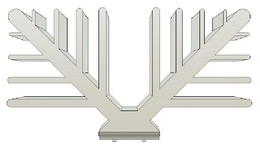
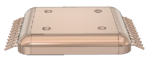
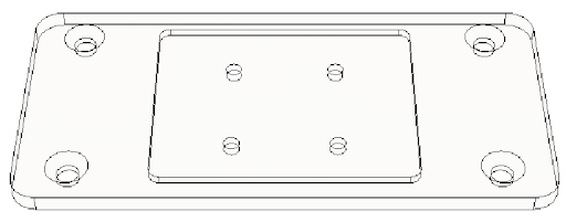
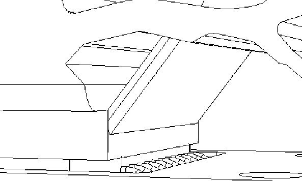
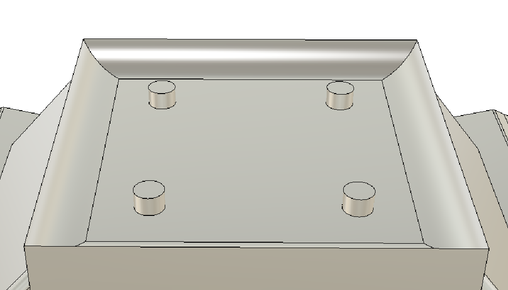
The models shown above were modeled by me in Fusion 360. These were used as the reference as to where to base our 3d-models from.
Original heatsink engineering specifications
Solution
For our design, we were able to lower the maximum temperature of the heatsink from 198°C → 132°C between the first and the last designs that we created.
With our main goal being to reduce the temperature as much as possible, we decided to set our heatsink material to copper alongside creating our design with thermal savings in mind. Throughout our entire process, our main focus was the movement of hot air throughout our entire heatsink from top to bottom.
My Role:
- Modelled the different root, stem, and shape iterations for the heatsink design
- Conducted simulations to test design iterations
- Researched various concepts relating to heatsink design and fluid thermodynamics
- Researched various methods of manufacturing
Background Research
To begin, our first challenge was to answer the question: How do we start to design a heatsink?
Modern heatsink designs for most CPUs generally involved several types: natural convection, fans, liquid cooling, or complex structures created through additive manufacturing to guide air through a specific path to cool the CPU located underneath.
Restrictions
- We are only able to use natural convection to cool our CPU. No fans or liquid.
- We are only able to use Fusion 360 to guide our decision-making process.
Currently on the market there are several types of heatsink designs that are used to cool down CPUs depending on the performance criteria, but generally natural convector heatsinks are used to cool down low temperature/performance CPUs.
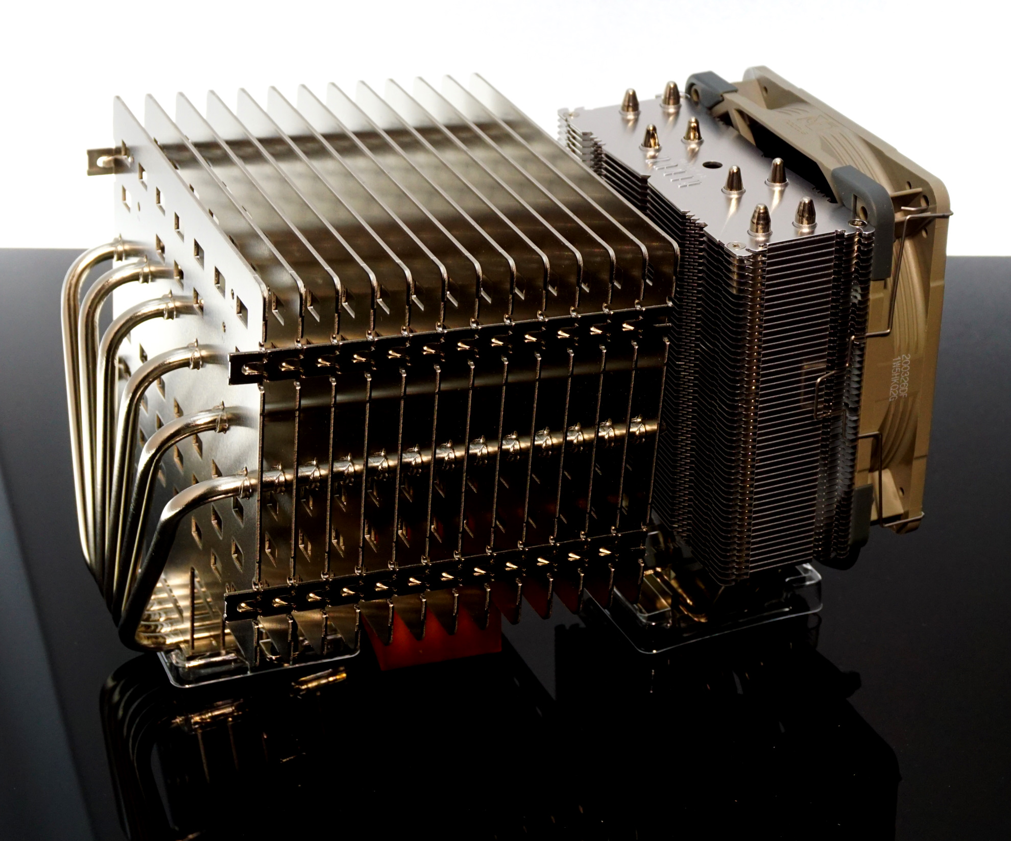
Noctua CPU cooler designed for natural convection alongside a fan
In my preliminary research, I found a variety of interesting articles and features regarding how natural convector heatsinks are designed. Generally, natural convection heatsinks are designed around thin, vertical fins that allow for the easy movement of air throughout the entire heatsink.
The goal is to facilitate the movement of hot air out of the top of the heatsink while making room for cold air to come in and fill the new space created. This allows the CPU to be cooled effectively and is crucial to creating a high functioning heatsink design.
Initial Heatsink Design & Iterations
From our research, we identified what we wanted to solve and the type of structure that we wanted to create in our design. But our goal was to make informed decisions on each of our features.
From the initial tree-like design, we modelled a variety of features onto the initial structure. From there we utilized Fusion360's thermal simulations to measure if the maximum temperature measured increased or decreased.
It is important to note, that Fusion360's thermal simulations is not a computational fluid simulation which resulted in inaccurate results. However, Fusion360 is a good first step towards getting a first version of our design.
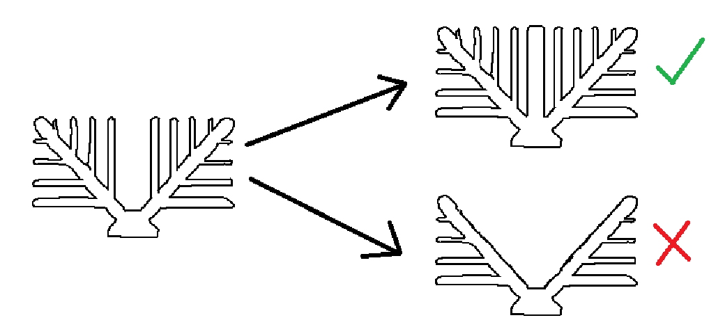
Holes
For optimal airflow, we experimented with different hole quantities throughout the entire design. The idea was to allow hot air to flow upward (buoyancy) between tree branches while reducing total volume:
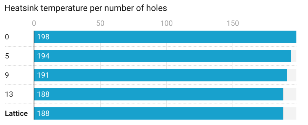
Iteration graph of number of holes in relation to temperature
Lattice Structure
During our research, we found many heatsink designs that utilized lattice structures alongside fans to optimize heat dissipation. In our case, since we decided to specify ourselves to only natural convection, a volumetric lattice would have many microstructures where airflow would be interrupted and become turbulent resulting in decreased performance.
Fins
Numerous characteristics of the fins, such as their quantity, curvature, and shape, were modified and fine-tuned using different models in Fusion 360. Each of these models where then compared directly to each other to see if a distnct different could be seen from different style fin geometries.
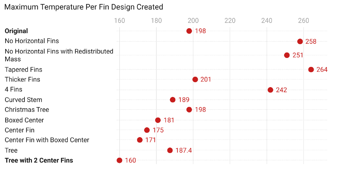
Temperature values simulated per iteration of our design
Topology Optimized Heatsinks
However, looking at the initial heatsink design, we were curious as to why it looked like a tree. Doing some further research, we found some really interesting articles based on optimized heatsink structures.
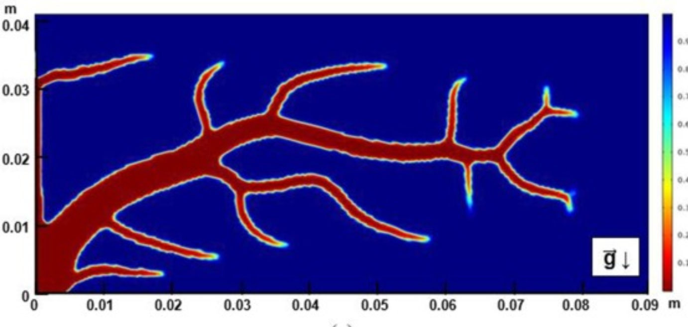
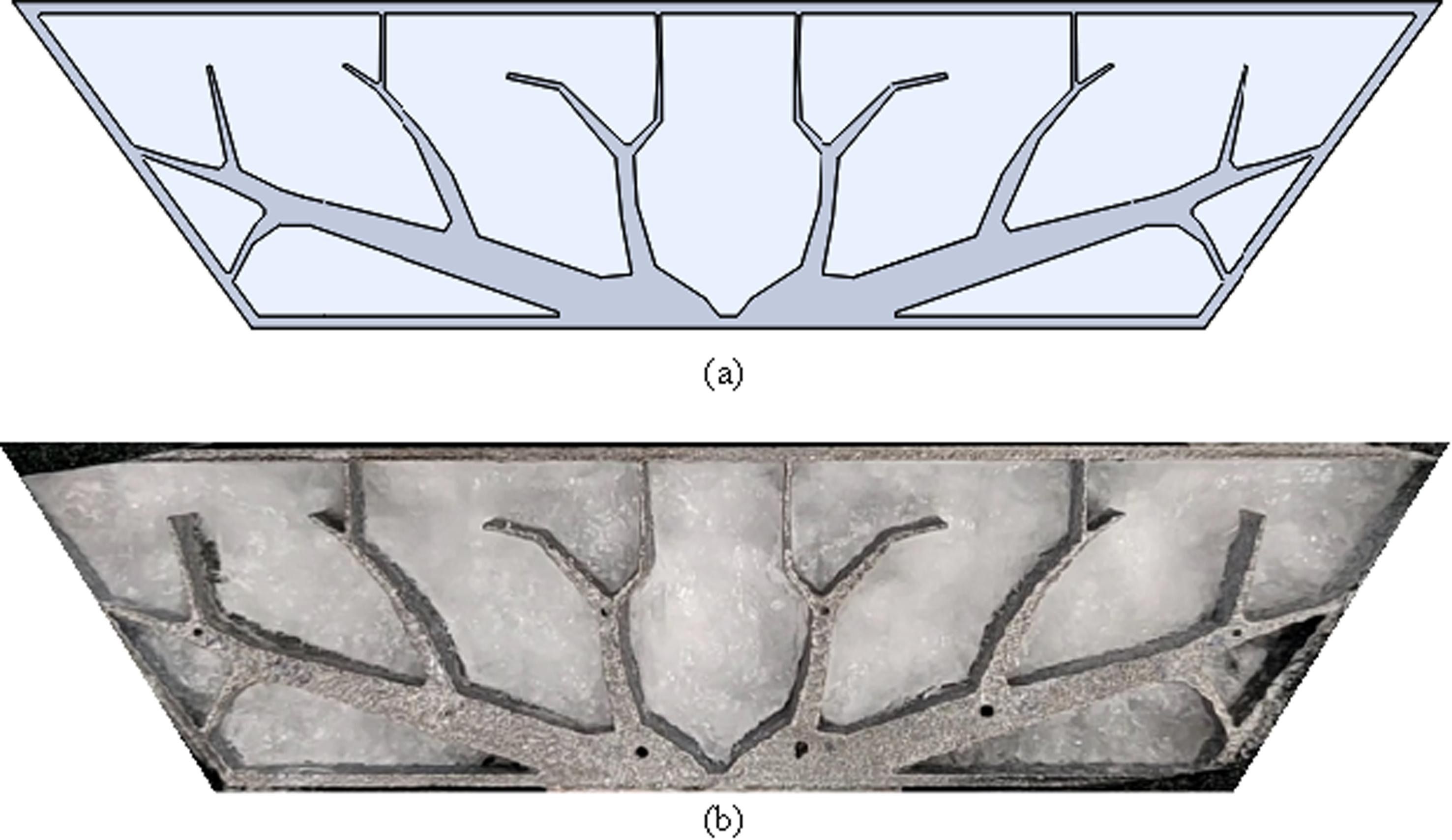
In an article written by Ho et al, using topology optimization and additive manufacturing, they found that a tree-like structure resulted in better thermal performance to dissipate heat from a chip.
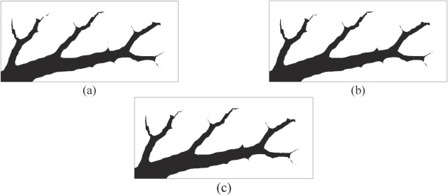
In another article written by Han-Ling Li et al, they utilized a black-box topology optimization simulation to create additional designs for natural convection problems:
Topology-optimized structures developed based on two-dimensional steady state heat transfer in the Ho et al study
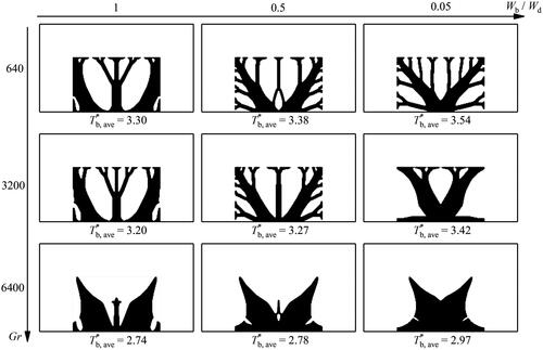
Designs obtained by TO for different heat sink volumes in the Han-Ling Li study
Designs obtained by TO for different heat sink volumes in the Han-Ling Li study
We found these structures really interesting due to their influence from nature and decided to model our final heatsink off of these structures.
Roots of the Tree
After completing our hole and fin design, we noticed that the hottest parts were at the bottom near the edges of the CPU where the heatsink was not touching and at the base.
Topology-optimized structures developed based on two-dimensional steady state heat transfer in the Ho et al study
Designs obtained by TO for different heat sink volumes in the Han-Ling Li study
To combat the high temperatures at the base, we experimented with adding different amounts of mass while keeping the tree branch design. We also saw that consistently the maximum temperatures in the overall assembly were found at the edges of the CPU that were in contact with air.
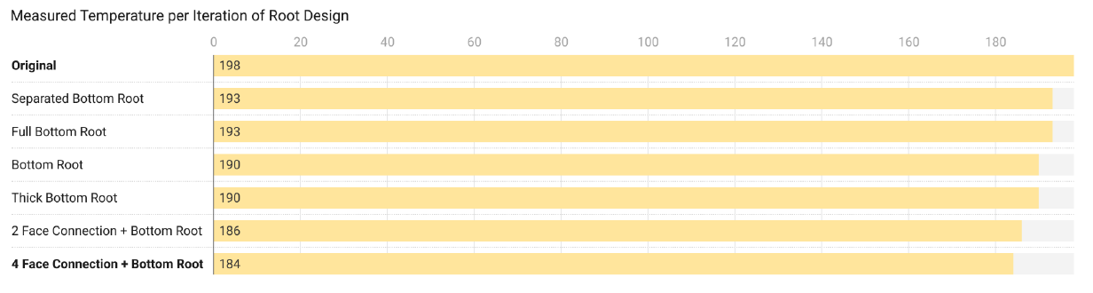
Temperature simulation per root design.
Final Design
Ultimately, we found ourselves being constrained by the time limit set by the challenge. We initially had one full week to complete our heatsink design but creating mini "studies" for each feature ate up a lot of the time we had.
Initial vs Final Temperature Results:
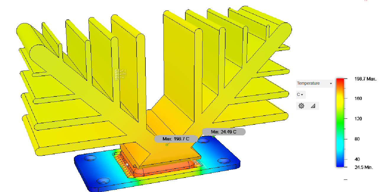
Temperature simulation for first deliverable
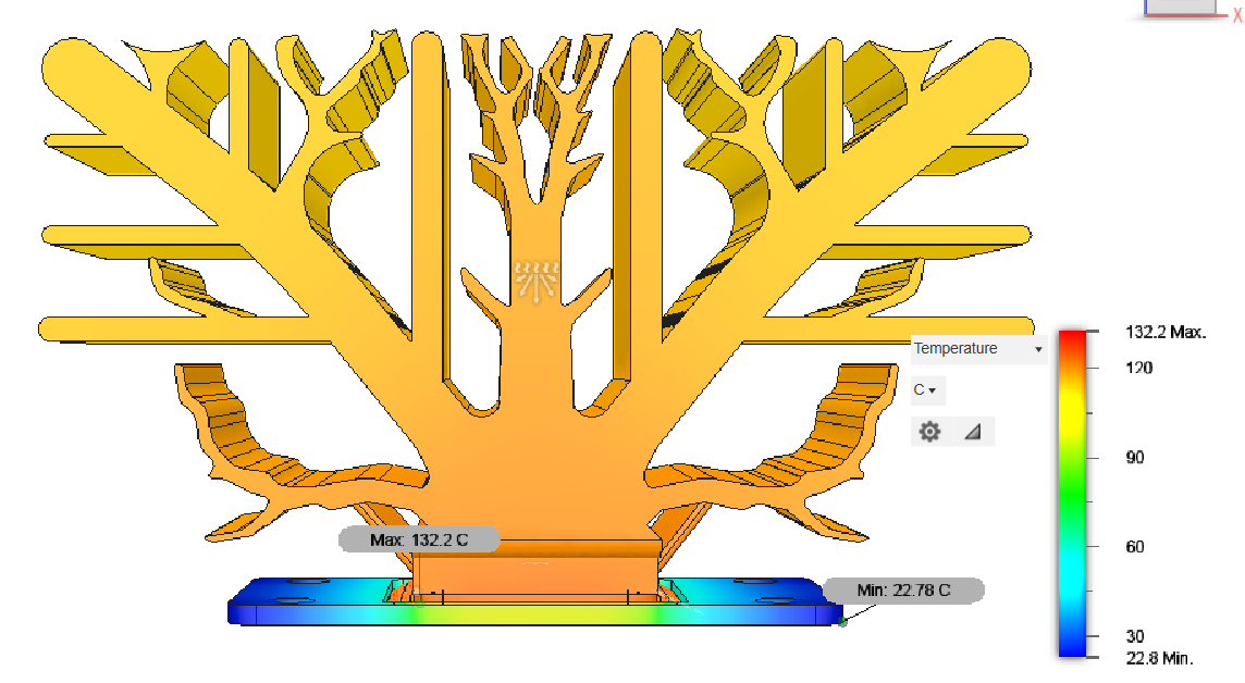
Temperature graph of final model
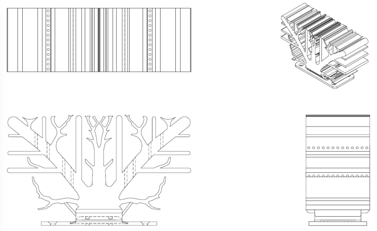
The final design multi-view drawing
Manufacturing
Initially, we assumed that metal 3D printing would solve all of our manufacturing concerns. Since we had internal holes and complex structures that would either be extremely difficult to manufacture.
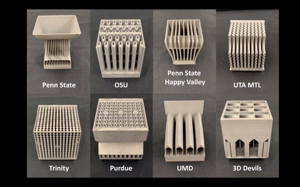
During our research, we saw a lot of really cool 3D printed designs for natural convection and fan powered CPU heatsinks for a variety of additive manufacturing competitions. Additionally, a lot of the tree-shaped optimized heatsinks also used SLM printing to create prototypes for their parts.
SLM printed topology optimized heatsink by See et al
However, since our main goal was to reduce the maximum temperature as much as possible, we decided that 3D printing would be feasible for prototyping but not for actually creating a mass-produced product due to concerns with porosity and lack of material selection.
CNC Milling
Advantages:
- High level of precision compared to other metalworking applications, allowing our prototypes to stay consistent and precise
Disadvantages:
- Expensive to program the path and to operate the machine
- Would require the part to be separated into different pieces that are machined separately
- Metal would be wasted as large blocks of metal are milled from a block, thus inefficient costs
- Extremely difficult to mill the holes between the heatsink fins, as new designs would be necessary to accommodate the mill
Injection Moulding
Advantages:
- Allows for lowered material use, creating less waste per volume
- Heatsink fin holes can be manufactured without complication by placing a cylinder inside of the mold
Disadvantages:
- Imprecise nature of the molding. However, since the final heatsink does not undergo any physical strain or hold fluids, it does not need to be extremely precise
- High porosity that would affect performance of the heatsink
- Difficult to mold pure aluminum and copper which results in porosity. Might be better to use an alloy instead
Materials
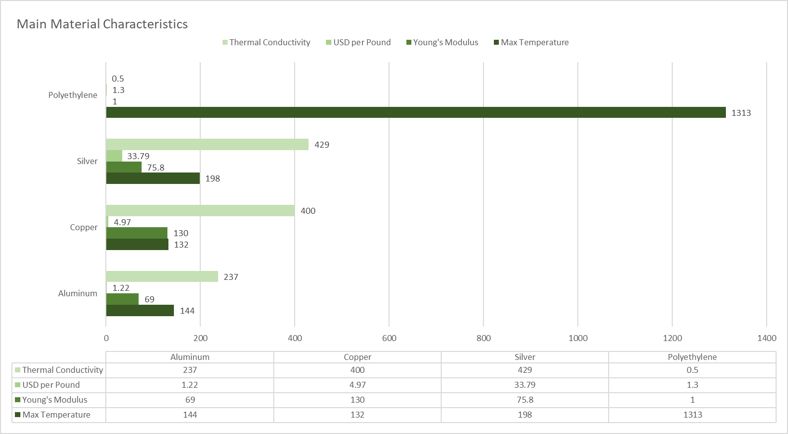
In the evaluation of materials for our heatsink design, some standard choices like aluminum, copper, and silver were considered.
Cost vs. Performance:
Copper offers superior thermal performance at a higher cost, while aluminum is the most affordable but less efficient in high-heat scenarios. Silver is too expensive for practical use despite its slight conductivity advantage over copper.
Manufacturability
- CNC: Copper is abrasive on tools but allows precise finishes, aluminum is easy to machine with low cost, and silver is soft, prone to deformation, and inefficient to machine
- Injection Moulding: Aluminum is by far the easiest to mold as copper has issues with oxidation, high melting points, and poor flow in molding processes
Another idea would be to create a heatsink with a mix of copper and aluminum. We would place copper near the CPU where more heat dissipation is required and aluminum on areas where performance is not as important.
This can be done through a specialized brazing and plating process to combine the two metals, but the research is still in early stages and not commercially viable.
Future Steps
- Running CFD simulations alongside thermal FEA simulations
- High-performance organizations, like F1 teams, develop algorithms to automate pre and post processing CFD simulations for their aerodynamic studies. To increase the efficiency of the workflow, scripts can be used to adjust boundary conditions and visualize data
- Black-box topology optimizations